

 EN
EN RU
RU

 Home/Blogs/Industry Knowledge/40.5kV Switchgear: Internal Arc Characteristics and Structural Protection
 February 05, 2026
In the design of 40.5kV Air-Insulated Switchgear (AIS), large internal clearances are typically reserved to ensure high electrical spacing and insulation reliability. While this approach enhances dielectric performance and reduces environmental interference, it introduces significant physical challenges. The expansive internal volume substantially alters the energy response characteristics during an internal arc fault, leading to a relatively weakened resistance against such failures. Consequently, critical measures must be implemented, such as installing insulation barriers between phases and to ground to limit arc energy, and reinforcing structural components including doors, beams, and enclosure panels.
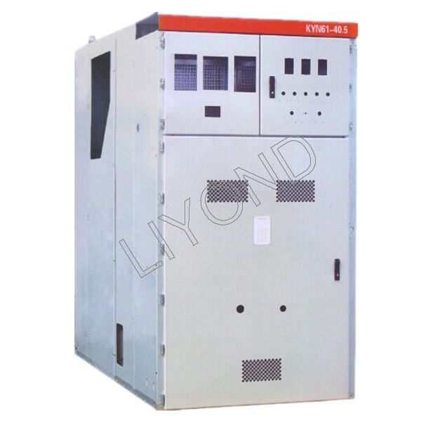
I. Relationship Between Switchgear Volume and Internal Arc Pressure
Contrary to a prevalent industry assumption, a larger medium voltage switchgear does not effectively “buffer” internal arc pressure. In fact, according to the requirements for extending the validity of internal arc fault type tests under IEC 62271-307, most key indicators demonstrate that large-scale structures are actually at a disadvantage when responding to internal faults.
The following is an in-depth analysis categorized by the core criteria of this standard (Clauses 1 to 13), revealing the stringent technical constraints faced by large-scale designs:
1. Insulation Performance and Electrode Clearance Constraints
- Phase-to-phase Clearance: Must be less than or equal to the prototype MV switchgear design. While larger spacing aids insulation, it directly elongates the arc path during a fault, causing a surge in arc voltage and total energy release.
- Phase-to-earth Clearance: Must remain identical.
- Insulation Materials Exposed to Arc: Must remain consistent.
2. Arcing Zone and Conductor Consistency
- Conductor Cross-sectional Area: Must be greater than or equal to the prototype design.
- Conductor Raw Material (Copper, Aluminum, or Alloy): Must be identical.
- Arc Ignition Point: Must be identical (adhering to IEC 62271-200 principles). These clauses ensure that the physical parameters at the onset of arcing remain controllable, preventing more complex arc propagation paths within large volumes.
3. Enclosure Volume and Mechanical Stability
- Net Volume of Enclosure and Compartments: Must be greater than or equal to the prototype design. Larger volumes mean increased surface area under pressure, placing higher demands on the overall structural topology.
- Strength of Enclosure and Compartments (including partitions and bushings): Must be greater than or equal to the prototype design.
- Thickness of Side Panels and Strength of Doors/Covers: Must be greater than or equal to the prototype design.
- Physical Challenge: As the surface area of the enclosure grows quadratically with size, the total force exerted on the panels under the same internal pressure becomes immense, easily leading to plastic deformation or structural failure.
4. Pressure Management and Energy Release Systems
- Relief Area: Must be greater than or equal to the prototype design. Due to the increased volume, the pressure wave travel path is longer, requiring relief channels with higher flow capacities and precise opening locations.
- Release Opening Pressure: Must be less than or equal to the prototype design (for fluid-sealed compartments).
- Fixing Strength of Relief Flaps: Must be less than or equal to the prototype design (for non-sealed compartments). This necessitates more sensitive relief devices to compensate for the dynamic loads caused by pressure wave accumulation in large-volume compartments.
II. Physical Mechanism of Switchgear Arc Energy Surges
The total energy released during an internal arc fault in switchgear is not determined by the system’s rated voltage, but rather by the arc voltage during the arcing process. Mechanically, arc voltage is directly proportional to the arcing path (electrode spacing). Therefore, in air-insulated systems, the increased phase spacing, intended to enhance dielectric strength, actually significantly increases the instantaneous power release during a fault. Comparative experiments show that at the same 31.5kA current, the arc energy generated in a 12kV switchgear is typically only about one-third of that in a 40.5kV enclosure.
III. Quantitative Calculation of Switchgear Internal Arc Parameters
According to metal clad switchgear manufacturers, through quantitative analysis of switchgear enclosures of varying widths, conclusions can be drawn from two theoretical models:
1. Based on the Arc Column Field Strength Empirical Model (approx. 13V/cm): For enclosure widths of 650mm, 800mm, and 1000mm, the calculated arc lengths are as follows:
- 650mm Width (40kA): Calculated arc voltage of 1862V, arc length of 143cm (1.43m).
- 800mm Width (31.5kA): Calculated arc voltage of 2181V, arc length of 168cm (1.68m).
- 1000mm Width (31.5kA): Calculated arc voltage of 2507V, arc length of 192cm (1.92m).
2. Based on the Inverse Formula for Electrode Net Clearance (Formula: Varc = (20 + 534 * g) * Iarc^0.12): Under the same conditions, the electrode net clearances (g) for the three spans are:
- 650mm Width: g = 0.94m.
- 800mm Width: g = 1.14m.
- 1000mm Width: g = 1.31m.

Observations demonstrate a positive correlation between electrode net clearance and enclosure width. Even if the arcing current does not increase, the total energy generated is extremely high. Relevant experiments prove that using arc-resistant insulation boards (such as GPO-3) to completely isolate phase-to-phase and phase-to-ground spaces can effectively limit the arc propagation length, thereby significantly reducing the total arc energy.
IV. Structural Strength and Pressure Relief Characteristics
Due to the significantly larger surface area of large-scale switchgear enclosures, their structural strength and impact resistance are relatively compromised. The moment an internal arc fault occurs is essentially a physical explosion, generating immense shockwave energy. Therefore, in the R&D of 40.5kV switchgear, the structure cannot simply be a scaled-up version of a 12kV enclosure without targeted reinforcement. Without measures such as thickening panels or adding stiffeners in the width direction, the structure will struggle to withstand the instantaneous pressure impact.
Regarding pressure relief design, the effectiveness of pressure relief is not solely a function of flap area. Relief devices must achieve millisecond-level precision opening during an internal arc fault to ensure rapid pressure release. At the moment of arcing, shockwaves radiate at extremely high speeds; typically, it takes only 5ms for the pressure wave in the busbar compartment to reach the relief flap. If the flap opens successfully at this point, the internal pressure will decay rapidly, thereby mitigating the destructive impact on other structural components.
Get A Free Quote


Power your projects with long-lasting switchgear and switchgear components from Liyond.
