

 EN
EN RU
RU

 Home/Blogs/Industry Knowledge/What is Disconnector: A Guide to Principles, Applications, and Operations
 January 21, 2026
The disconnector (also known as an isolating switch) is one of the most widely utilized switching devices in medium and high-voltage power systems. Its fundamental structure comprises a conducting system, insulating supports, a transmission mechanism, an operating mechanism, and a base frame. The most defining technical feature of a disconnector is the absence of a dedicated arc-extinguishing chamber, meaning it lacks the capacity to interrupt load currents or short-circuit currents. Within electrical installations, it is typically paired with a circuit breaker. Its core value lies in its ability to provide a physically visible break in the open position, establishing an air insulation gap that meets safety standards between decommissioned equipment and the energized grid.
1. Core Functions of Disconnectors
As critical control nodes within a power network, disconnectors play an irreplaceable, multi-dimensional role in system operation, configuration switching, and maintenance. Their core functions include:
- Safety Isolation: This is the most fundamental application. During equipment maintenance, the disconnector is used to reliably isolate the section under repair from other live parts. This visible break effectively prevents accidents caused by accidental closing or overvoltage breakdown, ensuring personnel safety.
- Switching Operations (Busbar Changeover): In double-busbar or multi-busbar configurations, disconnectors are used to transition energized equipment or transmission lines from one busbar to another, enabling flexible adjustment of the system’s operating mode.
- Interrupting Small Current Circuits: Despite lacking arc-extinguishing capabilities, disconnectors possess a limited capacity to make or break small inductive and capacitive currents. Typical scenarios include:
- Connecting or disconnecting potential transformers and surge arresters.
- Connecting or disconnecting the capacitive current of busbars and equipment directly connected to them.
- Connecting or disconnecting no-load transformers within specific limits (e.g., excitation current < 2A) or no-load lines (e.g., charging current < 5A).
- Automatic Rapid Isolation: In specific circuit configurations, disconnectors are used to swiftly isolate faulty equipment or lines, optimizing circuit breaker utilization while ensuring overall system stability.
2. Structural Composition of Disconnectors
The physical architecture of a disconnector is not merely a stack of components but a deeply integrated electromechanical system where each module follows rigorous logic for mechanical transmission and electrical insulation:
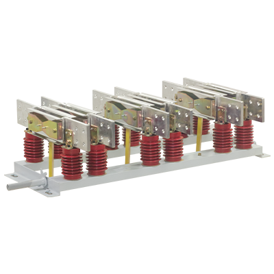
- Conducting System: Consists of contacts, blades (conductive rods), and terminal blocks. It is responsible for carrying normal operating currents and fault short-circuit currents while performing the closing and opening of the circuit.
- Insulation Components: Includes support insulators and operating insulators, ensuring dielectric strength between live parts and ground, as well as across the open gap.
- Transmission Mechanism: Composed of cranks, linkages, and shafts, this mechanism accurately transmits the torque from the operating mechanism to the contact system.
- Operating Mechanism: Provides the energy for the disconnector’s movement. Common types include manual, electric (motor-driven), pneumatic, or hydraulic drives.
- Support Base: Acts as the mechanical foundation, securing all components into a single unit for stable installation on supporting structures.
3. Classification and Characteristics of Disconnectors
To adapt to varying application environments, voltage levels, and installation requirements, disconnectors have evolved into several specialized types:
- By Installation Site:
- Indoor Type: Focused on compact design and dust-proofing, widely used in medium-voltage indoor switchgear or substations. These are typical representatives of medium voltage disconnectors, extensively applied in metal-enclosed switchgear units.
- Outdoor Type: Built with superior weather and corrosion resistance to withstand rain, snow, pollution, and icing; often equipped with specialized ice-breaking designs. Large-scale outdoor equipment usually falls under the category of high voltage disconnectors, engineered to endure the harsh conditions of high-voltage transmission grids.

- By Number of Support Insulators:
- Single-Column (Pantograph): Utilizes vertical space to form the gap; has a small footprint and is common in EHV (Extra-High Voltage) applications.
- Double-Column (Center-Break): Each pole has two support insulators; it is stable and remains the most widely used classic design.
- Triple-Column (Double-Break): Typically features a rotating center insulator for improved mechanical balance and service life.
- By Contact Trajectory:
- Horizontal-Break: Blades rotate in a horizontal plane, providing a clear gap and easy adjustment.
- Vertical-Break / Telescopic: Contacts open vertically. Telescopic designs effectively save horizontal space, making them ideal for narrow substation bays.
- Swing-Break: Blades move along a pendulum-like trajectory; simple in construction and often found in medium-voltage outdoor lines.
- By Poles and Earthing: Available in single-pole or three-pole configurations; can be equipped with no earthing, single-earthing, or double-earthing blades to ensure temporary grounding during maintenance.
4. Disconnector Typical Application Scenarios
In modern grid operations, disconnectors serve as the core hub for ensuring operational flexibility and maintenance safety. Their application spans the entire process from power generation to terminal distribution:
- Incoming and Outgoing Line Isolation: Deployed on either the line or load side of a circuit breaker. When the breaker requires routine maintenance or testing, the disconnector establishes a visible physical break to ensure the work environment is completely decoupled from the grid.
- Busbar System Transfers: In configurations with multiple busbars, the disconnector is the primary component for “changeover” operations. It allows operators to transfer circuit paths safely (often under specific interlock conditions) to maintain power continuity.
- Overhead Line Sectionalizing: Installed at sectionalizing points or branch junctions of long-distance transmission lines. They allow for the isolation of specific segments during faults or maintenance to minimize the outage area.
- Medium and High Voltage Switchgear: Integrated within medium voltage switchgear to isolate cable feeders or transformer branches, facilitating standard safety procedures like voltage testing and grounding.
- Transformer and Capacitor Bank Isolation: Used to connect or disconnect power transformers, arresters, and compensation capacitor banks, serving as the final physical defense line to ensure complete potential isolation.
5. Critical Technical Parameters of Disconnectors
When selecting equipment or evaluating operational status, the following core parameters must be strictly referenced:
- Rated Voltage and Current: Represent the maximum operating voltage the device can withstand and the maximum continuous current it can carry under specified temperature conditions.
- Rated Peak Withstand Current (Dynamic Stability): Reflects the device’s ability to withstand massive electrodynamic forces generated by short-circuit currents without mechanical damage.
- Rated Short-Time Withstand Current (Thermal Stability): The ability of the contacts to resist melting or damage when carrying short-circuit currents for a specified duration (usually 3-4 seconds).
- Contact Resistance: A key indicator of the quality of the electrical connection within the conductive path, reflecting manufacturing precision and assembly quality.
6. Technical Requirements for Disconnectors
Based on their role in the grid and service conditions, disconnectors must meet the following performance criteria:
- Clear Visible Break: Once open, there must be a distinct physical gap to allow personnel to verify the equipment is safely isolated.
- Reliable Dielectric Strength: The gap must have sufficient insulation distance to ensure no breakdown occurs under various overvoltage conditions.
- Short-Circuit Stability: Must possess adequate thermal and dynamic stability to prevent accidental opening due to electrodynamic forces during a fault.
- Specific Switching Capacity: Must be capable of interrupting specific capacitive, inductive, and circulating currents as rated.
- Operation Synchronicity: Excellent three-phase synchronicity and optimal operating speeds are required to minimize switching overvoltages and radio interference.
- Mechanical Reliability and Corrosion Resistance: Simple, reliable construction with high mechanical strength. Metal parts must be corrosion-resistant and capable of operating in freezing conditions.
- Comprehensive Interlocking:
- Must be equipped with interlocks ensuring the sequence: “De-energize: Disconnect first, then Earth; Re-energize: Break Earth first, then connect Disconnector.”
- Must be electrically interlocked with the circuit breaker to prevent “on-load” operation.
- Environmental Adaptability: Outdoor units must have rated ice-breaking capabilities and maintain sufficient creepage distances for polluted environments.
7. Operational Protocols and Safety Principles
Since disconnectors are paired with circuit breakers, strict adherence to interlocking logic is mandatory to prevent catastrophic “on-load” switching:
- Standard Operating Sequence:
- Power-Off (De-energizing): Must follow the sequence: Open Circuit Breaker -> Open Load-side Disconnector -> Open Source-side Disconnector.
- Power-On (Energizing): Must follow the sequence: Close Source-side Disconnector -> Close Load-side Disconnector -> Close Circuit Breaker.
- Verification Requirements:
- Before operating a disconnector, verify that the associated vacuum circuit breaker is in the OPEN position.
- Before closing a circuit breaker, verify that all associated disconnectors are fully CLOSED.
- Execution Details: Manual closing should be swift and decisive; manual opening should start slowly and then proceed rapidly once the contacts separate.
- Emergency Handling of Misoperation:
- Inadvertent On-Load Closing: If discovered mid-operation, NEVER re-open it. Complete the closing and then use the circuit breaker to interrupt the current.
- Inadvertent On-Load Opening: If an arc is noticed immediately upon separation, close it back instantly to extinguish the arc. If already fully opened, DO NOT attempt to close it again.
8. Maintenance and Inspection Procedures
To ensure long-term reliability, professional inspection and maintenance must focus on:
- Visual and Insulation Inspection: Check support insulators for cracks, discharge marks, or abnormal noise. Ensure corona rings are secure and leads show no signs of overheating or loose strands.
- Conductive Path Monitoring: Monitor operating temperatures (typically not exceeding 70°C) via infrared thermography. Check that contacts are fully seated in the jaws without deformation or loose bolts.
- Mechanical and Transmission Check: Inspect linkages and shafts for rust, deformation, or missing pins. For units with earthing switches, ensure solid three-phase contact in the grounded state.
- Secondary Systems: Ensure mechanism boxes are weather-sealed and heaters are functioning to prevent moisture.
- Environmental Maintenance: Increase inspection frequency during extreme weather (storms, heavy snow) or high-load periods. Perform periodic cleaning or water washing (for EHV equipment) as required.
9. Conclusion and Future Outlook
The disconnector remains a cornerstone of power system infrastructure, providing the critical physical break necessary for operational flexibility and safety. Through rigorous adherence to design standards, operational protocols, and maintenance schedules, its role as a vital safeguard in grid switching and maintenance can be fully realized.
As one of the electrical switchgear suppliers, Liyond is dedicated to providing high-quality disconnector solutions for the global power industry. We offer a comprehensive range of indoor and outdoor disconnectors across various voltage levels to meet the diverse needs of modern power systems. With extensive manufacturing expertise and stringent quality control, Liyond is your trusted partner for reliable power equipment. For product inquiries or technical support, please contact us.
Get A Free Quote


Power your projects with long-lasting switchgear and switchgear components from Liyond.
