

 EN
EN RU
RU

 Home/Blogs/Industry Knowledge/What Is Current Transformer Ratio? Basics, Calculation and Selection Guide
 July 07, 2026
In power systems, current transformers (CTs) play a vital role in monitoring, measurement, and protection by stepping down high primary currents to standardized, safer secondary current levels. The key parameter governing this conversion is the current transformer ratio (CT ratio), which determines whether downstream devices—including energy meters, measuring instruments, and protective relays—receive accurate current signals.
For electrical engineers and system designers, understanding and selecting the correct CT ratio is essential to ensuring measurement accuracy, reliable protection, and the safe operation of electrical power systems.
What Is Standard CT Ratio?
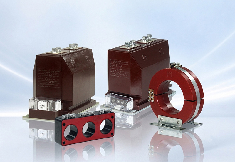
A current transformer operates on the principle of electromagnetic induction, using a magnetic core and windings to convert a high primary current into a proportional low secondary current. The standard CT ratio, also referred to as the CT turns ratio or CT transformation ratio, is the ratio of the rated primary current to the rated secondary current, expressed as:
K = Ip / Is
Where:
Ip = Rated primary current
Is = Rated secondary current
From a construction perspective, this ratio is determined by the number of turns in the transformer’s windings. The primary winding typically consists of only a few turns and is connected in series with the main circuit, while the secondary winding contains many more turns. Because the primary winding has significantly fewer turns than the secondary winding, the CT proportionally reduces high primary currents to standardized secondary currents of 5 A or 1 A.
For example, a 500/5 A current transformer delivers 5 A on the secondary side when the primary current reaches 500 A. This proportional current conversion enables measuring instruments, control devices, and protective relays to operate within standardized current ranges while providing electrical isolation from the high-current primary circuit.
During normal operation, the CT secondary circuit operates under conditions close to a short circuit because the connected burden has very low impedance. The secondary circuit must never be left open while the primary circuit is energized, as doing so can generate dangerously high voltages across the secondary terminals.
How to Calculate and Select CT Ratio?
Selecting the appropriate CT ratio involves more than simply matching current values. The selected ratio should be capable of carrying the maximum operating current while maintaining measurement accuracy under normal operating conditions and meeting the requirements of the protection system during fault conditions. In practice, CT ratio selection should take into account the load characteristics of the primary circuit, the burden of the secondary circuit, and the expected operating conditions to ensure long-term system reliability and performance.
How to Calculate CT Ratio?
The CT ratio (K) is primarily determined by the maximum expected load current on the primary side. As a general guideline, the CT should be selected so that, under normal operating conditions, the secondary current remains within approximately 60% to 100% of its rated output (typically 5 A or 1 A). This allows the current transformer to operate within its optimal accuracy range.
The basic calculation is:
K = Ip / Is
Where:
Ip = Rated primary current, selected based on the maximum continuous load current of the circuit. In practice, the chosen standard primary current rating should be equal to or slightly higher than the maximum expected operating current.
Is = Rated secondary current, determined by the input rating of the connected measuring or protection equipment. The standard secondary current is typically 5 A or 1 A.
CT Ratio Selection Considerations
After calculating the required CT ratio, the selected specification should be verified against the actual operating conditions to ensure both measurement accuracy and practical suitability for the application.
Primary Current Matching: The rated primary current should be greater than or equal to the circuit’s maximum operating current, but it should not be excessively oversized. An oversized CT ratio may reduce measurement accuracy under light-load conditions, while an undersized ratio can lead to prolonged overload during normal operation. In protection applications, it may also cause the CT to saturate prematurely during fault conditions, affecting the correct operation of protective relays.
Selecting the Secondary Current (1 A or 5 A): Current transformers are commonly available with 1 A or 5 A rated secondary outputs. A 1 A secondary is generally recommended for installations with long secondary cable runs, as it reduces voltage drop and power loss in the secondary circuit. A 5 A secondary remains the preferred choice for shorter cable runs and for compatibility with many conventional meters and protection relays. Therefore, both the CT ratio and the appropriate secondary current rating should be determined during the selection process (for example, 100/5 A or 100/1 A).
Adjusting the Ratio of Window-Type CTs: For window-type current transformers, the effective CT ratio can be adjusted by changing the number of turns of the primary conductor passing through the CT window. For example, if the primary conductor passes through a 200/5 A CT twice, the effective ratio becomes approximately 100/5 A. This provides greater flexibility during installation. However, sufficient installation space and the minimum bending radius of the conductor should always be considered before adopting this approach.

Prefer Standard CT Ratios: Whenever possible, standard CT ratios such as 50/5 A, 100/5 A, 200/5 A, 300/5 A, and 400/5 A (or their 1 A equivalents) should be selected. Standardized ratios simplify procurement, spare parts management, future maintenance, and equipment replacement while improving overall compatibility across the system.
Verify Other CT Parameters: Once the CT ratio has been selected, other technical parameters should also be verified according to the application requirements. These include the CT accuracy class, rated burden, insulation level, and protection characteristics to ensure the current transformer meets the overall performance requirements of the metering or protection system.
Common Applications of CT Ratio
The principles of CT ratio selection apply across a wide range of electrical systems. However, different applications have different load characteristics and operating requirements, so the selection criteria may vary accordingly. The following examples illustrate how CT ratios are typically selected for energy metering systems and medium-voltage distribution systems.
CT Ratio for Energy Meter
In energy metering applications, the primary objective of CT ratio selection is to maintain measurement accuracy by ensuring that the current transformer operates within its optimal measuring range during normal operation. As a general engineering guideline, the normal load current should be maintained at approximately 60% to 90% of the CT’s rated primary current to achieve a good balance between measurement accuracy and operational stability.
When selecting a CT ratio, avoid choosing an excessively large ratio simply to accommodate potential future expansion. Instead, select a standard CT ratio that closely matches the actual load while allowing a reasonable margin for future load growth. An oversized CT ratio may reduce metering accuracy under light-load conditions, whereas an undersized ratio may exceed the CT’s rated current during future load increases or temporary overloads, affecting normal measurement performance.
CT Ratio for 11 kV and 33 kV Systems
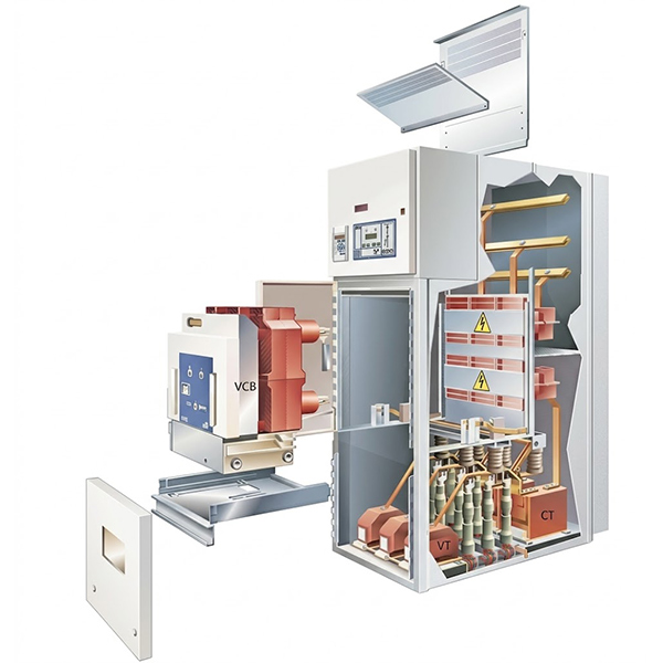
For medium-voltage switchgear such as 11 kV and 33 kV, the CT ratio should be selected based on the maximum continuous current of the feeder or circuit rather than the system voltage itself. Even within the same voltage class, different feeders may require different CT ratios because of variations in load capacity.
In engineering practice, it is recommended to select a standard CT ratio that satisfies the current load requirements while allowing reasonable capacity for future system expansion. Common choices include 200/5 A, 400/5 A, and 600/5 A, depending on the expected operating current. This approach not only meets the requirements for routine monitoring and energy metering but also helps minimize replacement costs during future system upgrades and improves the overall flexibility of the electrical system.
Conclusion
The CT ratio is one of the most important parameters when selecting a current transformer, directly affecting the performance of energy metering, current measurement, and protection systems. Whether calculating a CT ratio or selecting a standard CT ratio, the decision should be based on the actual primary load current while also considering the rated secondary current, standard CT ratings, and future load growth.
A properly selected CT ratio helps improve measurement accuracy, enhances system reliability, and reduces long-term maintenance and upgrade costs. It is also important to recognize that there is no single standard CT ratio suitable for every application. The final selection should always be based on the actual operating conditions, system requirements, and engineering considerations.
If you are selecting a current transformer or need assistance in determining the most suitable CT ratio for your application, Liyond, a professional current transformer manufacturer, can provide expert product selection support and technical guidance to help you choose the right solution for your project.
Get A Free Quote


Power your projects with long-lasting switchgear and switchgear components from Liyond.
