

 EN
EN RU
RU


September 04, 2025
In modern power systems, instrument transformers are critical electrical devices that precisely convert high voltage or large currents into safe, standardized low-voltage or low-current signals. They primarily serve the purposes of measurement and protection. Acting as a bridge between dangerous high-voltage primary circuits and low-voltage secondary equipment, they ensure the safety of personnel and the reliable operation of the entire system. Instrument transformers are foundational to the precise monitoring and effective control of the power grid.

How Instrument Transformers Work
The core principle behind instrument transformers is electromagnetic induction, similar to conventional power transformers. However, their design and purpose are more focused on providing accurate and stable current or voltage signals, rather than simple energy transfer. Based on the parameters they measure, instrument transformers are divided into Current Transformers (CTs) and Voltage Transformers (VTs), each with fundamental differences in their working principle, structure, and wiring.
Current Transformer Working Principle
To understand how current transformers work, it’s important to know that current transformers are primarily used for measurement and protection, working by converting a large current into a small one. The CT’s primary winding is connected in series with the main power circuit and typically has very few turns. The secondary winding, which has many more turns, is connected to a measuring instrument or a protection device. When a large current flows through the primary side, it generates a magnetic flux in the iron core that is proportional to the primary current. This flux induces a proportional secondary current in the secondary winding. A precise turn ratio allows for accurate conversion of large currents to small currents.
More about What Is the Function of a Current Transformer
Voltage Transformer Working Principle
VTs, sometimes called potential transformers (PTs), are also used for measurement and protection, working by converting a high voltage into a low voltage. The VT’s primary winding is connected in parallel with the main power circuit and has many turns. The secondary winding, which has fewer turns, is connected to a measuring instrument or a protection device. When the primary side is subjected to high voltage, it generates a magnetic flux in the iron core. This flux induces a secondary voltage in the secondary winding that is proportional to the primary voltage. In this way, high voltage can be safely and accurately converted into a low voltage for use by secondary equipment.
Although CTs and VTs have different operating principles, their fundamental purpose is to provide accurate and reliable signals for measurement and protection systems through precise proportional conversion, all while ensuring electrical isolation and safety. The design of instrument transformers is always centered on two key goals: safety, by physically isolating the high-voltage primary circuit to protect downstream equipment and operators, and accuracy, by ensuring the converted signal is highly precise, which is the basis for accurate metering and reliable relay protection.
Instrument Transformer Applications
As a crucial component of power transmission and distribution networks, the applications of instrument transformers extend far beyond power plants and substations. Their core function is to provide accurate data and safety assurance for various downstream systems.
- Energy Metering: Instrument transformers provide precise current and voltage signals to energy meters, ensuring the accuracy of commercial energy billing. In this application, the high-precision characteristics of the transformer are vital, as they directly relate to the fairness of electricity transactions and the reliability of data.
- Relay Protection: Instrument transformers are a key component of relay protection systems. Their core function is to monitor and respond to abnormal conditions in the power grid. When a short circuit, overload, or ground fault occurs, the transformer accurately transmits the abnormal current or voltage signal to the protection device, prompting it to act quickly and disconnect the fault circuit. This prevents equipment damage and system collapse, ensuring the stability of the entire grid.
- Monitoring and Control: Through the real-time data provided by instrument transformers, grid dispatchers can continuously monitor the operational status of the power system, including key parameters like voltage, current, and power factor. This data is the basis for load forecasting, optimizing power dispatch, and remote control, providing a foundation for stable grid operation. In industrial automation and building management systems, instrument transformers are also used to provide real-time data for refined management and control of energy consumption.
- Power and Frequency Measurement: Instrument transformers provide the necessary signals for power and frequency meters. Signals from both CTs and VTs can be used to accurately measure the active power, reactive power, and power factor of the power system. These signals also form the basis for frequency measurement equipment, ensuring the power system operates at a stable frequency.
- Expanding Applications in New Energy and Industry: The applications of instrument transformers have also expanded widely into non-traditional fields. In areas such as new energy generation (e.g., wind and solar), rail transportation, large-scale industrial projects, and electric vehicle charging stations, instrument transformers are essential components whose reliability is directly linked to the operational safety of these critical infrastructures.
The applications of instrument transformers span the entire power chain, from generation and transmission to distribution and end-use. They are not only the cornerstone of safe and efficient grid operation but also key sensors driving the digital transformation of smart grids and energy systems, providing data support and control for the future of energy.
Advantages of Instrument Transformers
Instrument transformers play an indispensable role in modern power systems. Their core advantages lie in ensuring the safety, accuracy, and efficiency of power transmission and distribution. These advantages collectively constitute the irreplaceable value of instrument transformers in the power industry.
- Safety Isolation: Through their unique structure, instrument transformers provide physical isolation between the high-voltage primary circuit and the measuring and protection systems. This feature allows operators to perform maintenance and data readings in a safe, low-voltage environment, greatly reducing the risk of electric shock and protecting personnel and sensitive downstream equipment.
- High Accuracy: As a data source for the power system, instrument transformers can provide highly precise current and voltage signals, with their accuracy class directly affecting the accuracy of energy metering. High-precision transformers ensure the integrity of grid data, providing a reliable basis for fair electricity transactions, precise system control, and energy efficiency analysis.
- Standardized Output: Instrument transformers convert various voltage levels and large currents into industry-standard signals (e.g., 5A or 1A current, and 100V voltage). This allows for the standardization of secondary devices (such as meters and relays), which greatly simplifies system integration and maintenance, reduces costs, and ensures equipment interchangeability.
- High Reliability and Durability: Instrument transformers are typically made with robust insulation materials and structural designs, allowing them to operate stably for extended periods in harsh environments (e.g., extreme temperatures, high humidity, or severe vibration). Outdoor instrument transformers use special weather-resistant materials and sealing technologies, such as silicone rubber, composite insulators, and multi-layer sealing structures, to resist rain, ultraviolet radiation, salt spray corrosion, and temperature fluctuations, ensuring long-term stable operation in demanding outdoor conditions.
- Compact Structure: Especially for indoor transformers, the design philosophy pursues high integration and miniaturization. They can effectively utilize the limited space in MV switchgear and distribution cabinets without sacrificing performance, reducing installation difficulty and space costs. This is a key aspect of the miniaturization of modern electrical equipment.
Instrument transformers, with their outstanding performance, play an indispensable role in modern power systems. Their core advantages of safety isolation, high accuracy, and standardized output not only guarantee the integrity and safety of grid data but also ensure the stability and efficient operation of the power system. Furthermore, their high reliability and compact structure allow them to adapt to complex environments and the trend towards miniaturization, collectively laying a solid foundation for the smart grid and digital energy transformation.
Instrument Transformer Diagrams
Technical diagrams of instrument transformer products provide a direct way to understand their internal structure, wiring methods, and physical dimensions. These visuals are an indispensable part of understanding and evaluating instrument transformer products. They not only offer a straightforward visual reference but also translate complex technical parameters and physical dimensions into actionable engineering information, which is a crucial basis for technical personnel during product selection, project planning, and ensuring equipment compatibility. Diagrams make abstract technical concepts tangible, significantly enhancing communication efficiency and laying a solid foundation for successful project implementation.
Current Transformer (CT) Diagram
Taking the LZZBJ9-10AG type current transformer as an example, its diagram clearly shows the product’s physical dimensions and installation details. From the illustration, it’s clear that the transformer uses a compact cast insulation design, so we can also call it as resin cast current transformer. The diagram indicates its external dimensions (e.g., mm x mm) and mounting hole positions (e.g., 4-M12 bolt holes), providing engineers with precise installation information. In addition, the diagram also labels the two terminals of the primary winding (P1 and P2), which directly corresponds to the transformer’s series connection method in the main circuit.
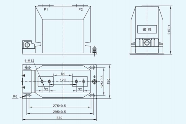
These technical diagrams are an indispensable part of understanding and evaluating instrument transformer products. For current transformers, diagrams clearly show key information such as the core series connection, physical dimensions, and mounting holes, which are crucial for ensuring the product can be perfectly integrated into existing distribution or switch cabinets. Through diagrams, technical personnel can visually verify the product’s compatibility and ease of installation, thereby ensuring the smooth implementation of the project and the reliable operation of the equipment.
Voltage Transformer (VT) Diagram
Taking the JDZX10-3, 6, 10 type voltage transformer as an example, its diagram illustrates the product’s wiring method, dimensions, and technical parameters. The diagram clearly shows its parallel connection method and the multiple secondary winding output terminals (e.g., a, n, da, dn). These details are crucial for understanding how the transformer is precisely connected in parallel to the main circuit and how it connects to downstream measuring and protection equipment. The diagram also provides product dimensions (e.g., mm x mm), which helps engineers in the project design phase to make precise space plans and ensures the product can be seamlessly integrated into existing systems.
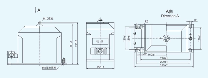
These technical diagrams are a core reference in product selection and project implementation. For voltage transformers, diagrams can intuitively show the structure of their parallel connection and multiple secondary windings, which is vital for understanding and evaluating how the product safely and accurately connects to high-voltage systems and provides standard signals for multiple protection and measurement devices. Through diagrams, technical personnel can effectively assess the product’s applicability, installation feasibility, and compatibility with existing systems, which is key to ensuring the smooth progress of the project and the long-term reliable operation of the equipment.
Technical diagrams of instrument transformers are more than just simple technical appendices; they are a bridge connecting product specifications with practical application scenarios. They make abstract technical parameters tangible, allowing engineers and technical personnel to overcome language and text barriers and visually assess a product’s physical compatibility, installation feasibility, and integration capabilities with existing power systems. Whether for precise space planning for complex projects or for quickly confirming wiring methods on site, these diagrams provide an indispensable visual basis, which greatly improves decision-making efficiency and project reliability.
Instrument Transformer Technology
Instrument transformer technology is undergoing a profound transformation, with its development closely linked to the progress of grid technology. From early traditional electromagnetic transformers to modern intelligent transformers that integrate electronic, optical, and digital communication technologies, innovation has not only improved product performance but also laid the foundation for the future development of power systems.
Instrument transformer technology is undergoing a profound transformation, with its development closely linked to the progress of grid technology. From early traditional electromagnetic instrument transformers to modern intelligent ones that integrate electronic, optical, and digital communication technologies, innovation has not only improved product performance but also laid the foundation for the future development of power systems.
Innovations in Insulation Technology
Insulation material is at the heart of an instrument transformer’s safety and reliability. Technological development has moved from traditional insulation methods toward more environmentally friendly and safer alternatives.
- Oil-Immersed Instrument Transformers: Use transformer oil as an insulation and cooling medium. Although mature and time-tested, they pose risks of leakage and environmental pollution.
- Cast-Insulated Instrument Transformers: Use epoxy resin and other insulating materials to cast the windings and iron core as a single, solid insulated structure. This technology eliminates the risk of oil leakage, is compact, requires minimal maintenance, and has good fire resistance. It is the dominant technology for indoor instrument transformers.
- Gas-Insulated (GIS) Instrument Transformers: Integrate the transformer into a sealed tank filled with SF6 gas, achieving high integration and reliability. These instrument transformers are compact, unaffected by the external environment, and are often used in compact substations and locations with strict space requirements.
The Fusion of Digitalization and Intelligence
Traditional instrument transformers provide analog signals for grid operation, while intelligent instrument transformers convert these signals into data that can be processed directly by digital systems. They use fiber optic networks for transmission, enabling the comprehensive digitalization of the power grid.
- Electronic Instrument Transformers (EITs): Use electronic components and optical principles for measurement, replacing traditional electromagnetic instrument transformers. For example, Rogowski coil-based current sensors and resistor-divider-based voltage sensors offer advantages such as no saturation, high linearity, and a wide dynamic range.
- Digital Output: A core feature of EITs is their direct digital output (e.g., IEC 61850-9-2), which allows them to seamlessly integrate into digital substations, enabling real-time information sharing and remote control.
- Condition Monitoring and Diagnostics: Intelligent instrument transformers have built-in sensors and communication modules that can monitor their own operational status in real-time (e.g., temperature and vibration). By analyzing this data, they can provide fault warnings and lifetime predictions, transitioning maintenance from a reactive to a proactive, predictive approach.
The Trend Towards Miniaturization and Passive Technology
To adapt to the increasing space pressure and efficiency requirements of urban power grids, instrument transformer technology is moving towards miniaturization and passive technology.
- Compact Structural Design: The new generation of instrument transformers, especially indoor products for medium-voltage applications, are more compactly designed to effectively utilize the limited space within distribution cabinets, reducing installation difficulty and space costs.
- Passive Technology: Some new sensors, such as fiber-optic based ones, do not require an external power supply, which simplifies the design, reduces energy consumption, and enhances reliability in extreme environments.
Maintenance and Common Faults of Instrument Transformers
The long-term reliable operation of instrument transformers relies on proper daily maintenance. Regular preventive maintenance, such as insulation testing, visual inspections, and cleaning, can help identify and resolve potential problems in time, preventing small faults from escalating into major accidents.
Key Points for Preventive Maintenance
- Visual Inspection: Regularly check the exterior of the transformer for cracks, dirt, discharge traces, or loose fittings.
- Insulation Testing: Periodically perform insulation resistance tests to assess the insulation status and prevent faults caused by insulation aging or moisture.
- Temperature Monitoring: During operation, pay attention to the transformer’s temperature rise. Abnormal temperatures may indicate an internal overload or insulation problem.
Common Faults and Prevention
While instrument transformers are inherently very reliable, some faults can still occur under certain conditions. Understanding these can help with early detection and prevention:
- Insulation Aging: This is one of the most common causes of transformer failure. It can be effectively monitored and prevented through regular insulation testing.
- Overload and Temperature Rise: Long-term overload can lead to winding overheating, accelerating insulation aging.
- Open-Circuit in Secondary (CT) or Short-Circuit (VT): These are serious abnormalities during transformer operation and must be strictly avoided. The secondary side of a current transformer must not be open-circuited, as this will generate a high voltage that endangers equipment and personnel. The secondary side of a voltage transformer must not be short-circuited, as this will damage the equipment.
Main Structural Types of Instrument Transformers
Instrument transformers come in a variety of structures, primarily distinguished by their insulation method and installation environment to meet the needs of different application scenarios. Understanding these instrument transformer types helps users select the right product for their specific needs.
1. Oil-Immersed Transformers
This is a traditional structural type that uses transformer oil as the primary insulation and cooling medium. The iron core and windings are submerged in an oil tank, and the oil’s convection dissipates the heat generated during operation.
- Advantages: Excellent insulation performance, high heat dissipation efficiency, and mature and reliable technology. Often used for high-voltage outdoor installations.
- Disadvantages: Risks of oil leakage and fire, requires periodic oil quality inspection and maintenance, and is relatively large and heavy.
- Typical Applications: Primarily used in outdoor substations and high-voltage transmission lines, especially in scenarios that handle high power and high voltage.
2. Dry-Type Transformers
Dry-type transformers do not use insulating oil. They typically use epoxy resin and other insulating materials to cast the windings and iron core, forming a sturdy solid insulated structure.
- Advantages: Maintenance-free, good fire resistance, compact and lightweight, no risk of oil leakage or environmental pollution, and can be installed in locations with strict fire safety requirements.
- Disadvantages: Heat dissipation is not as efficient as oil-immersed transformers, so they are typically used for medium- and low-voltage applications.
- Typical Applications: Widely used in indoor distribution and switch cabinets, as well as in industrial and civil buildings with high demands for space and environmental conditions.

3. GIS (Gas-Insulated Switchgear) Integrated Transformers
GIS-integrated transformers are installed inside a gas-insulated switchgear, typically using sulfur hexafluoride (SF6) gas as the insulating medium (SF6 gas insulated switchgear). This structure encapsulates the transformer with components like circuit breakers and disconnectors in a single airtight enclosure.
- Advantages: Compact, highly integrated, unaffected by the external environment, extremely safe and reliable, requires minimal maintenance, and has high anti-pollution flashover capability.
- Disadvantages: Complex technology, higher cost, and requires specialized GIS equipment.
- Typical Applications: Suitable for urban substations with limited space, underground substations, and critical power facilities with extremely high requirements for safety and reliability.
These common structural types of instrument transformers are designed for different insulation methods and application environments, each with unique advantages and suitable scenarios. In project planning and equipment selection, choosing the appropriate transformer based on the system’s specific needs and environmental characteristics is crucial for ensuring the safe and stable operation of the power system. As a professional instrument transformer manufacturer, we offer a wide range of voltage and current transformers with various insulation and specifications to meet diverse engineering needs. You can use the information in this article to get a preliminary understanding of the products, or you can contact us directly for professional selection advice and product information.
Summary
Instrument transformers are the cornerstone of modern power systems. Their core value lies in providing precise conversion and safe isolation from high voltage and large currents to safe, standard signals. With the two fundamental types, Voltage Transformers (VT) and Current Transformers (CT), they provide a reliable data source for energy metering, relay protection, and monitoring and control of the power grid. With technological advancements, instrument transformers have evolved from traditional electromagnetic types to smart, digital ones. Their insulation technology is constantly being innovated, and their functions continue to expand, playing a crucial role in ensuring safe, stable, and efficient grid operation. Ultimately, whether through their excellent performance advantages or their diverse structural types, instrument transformers are providing solid support for the digitalization and smart transformation of the power grid.
Get A Free Quote


Power your projects with long-lasting switchgear and switchgear components from Liyond.
