

 EN
EN RU
RU


March 26, 2026
Medium-voltage Cubicle Gas-Insulated Switchgear (C-GIS) is a sophisticated assembly where core components are encapsulated within a stainless steel enclosure filled with insulating gas. Renowned for its safety, reliability, maintenance-free nature, and compact footprint, C-GIS is widely deployed in harsh or specialized environments, including high-temperature, high-humidity, salt-mist, and space-constrained conditions.
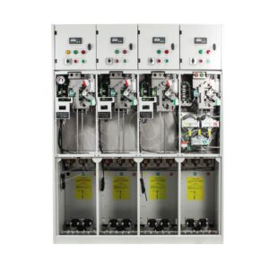
The operational stability, dielectric performance, and service life of C-GIS are directly dictated by the precision of key manufacturing processes. Core stages—including enclosure welding, gas processing, insulation assembly, and sealing protection—are the ultimate determinants of product quality. By integrating industry standards with manufacturing best practices, this guide analyzes the critical control points of C-GIS production to identify common process challenges and formulate effective optimization measures.
I. GIS Enclosure Fabrication and Welding Process Control
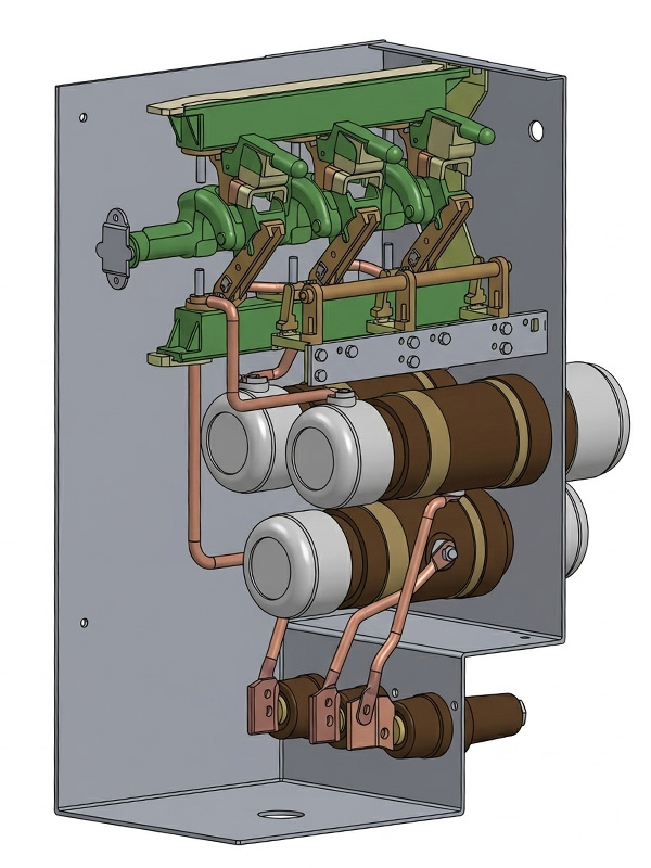
The C-GIS enclosure functions as both a hermetic pressure vessel for the insulating gas and a high-precision structural backbone for mounting core components, such as vacuum circuit breaker, disconnector switch, and earthing switch. It must simultaneously satisfy stringent requirements for gas-tightness, mechanical strength, and dimensional precision. The fabrication and welding of the enclosure constitute the heart of the production line and represent the first line of defense against gas leakage and moisture ingress.
(A) Material Cutting and Forming Control
Enclosures are typically fabricated from 3mm thick high-grade stainless steel plates. The precision of material cutting and forming directly influences the hermetic integrity of subsequent welds and the overall structural accuracy.
- Cutting Precision: Laser cutting is the preferred method to ensure smooth, burr-free edges. Cutting tolerances should be strictly maintained within ±0.1mm. Insufficient precision at this stage can lead to excessive joint gaps, which invariably cause welding defects.
- Forming Control: CNC bending equipment should be utilized for enclosure shaping. Strict control over bending angles and radii is essential to prevent stress concentrations, cracks, or wrinkles. For critical components like side panels, single-piece fabrication is recommended over multi-piece splicing to minimize residual stress.
(B) Welding Process Control
The primary objective of the welding process is to achieve a fully hermetic structure. Laser welding is the industry preference over traditional methods due to its narrow weld seams, low heat input, minimal thermal distortion, and high aspect ratio—qualities that favor high-volume, high-quality production.
- Joint Gap Requirements: Welding quality is highly sensitive to cutting precision and fit-up gaps. If the joint gap exceeds 0.3mm, the risk of welding defects and compromised gas-tightness increases significantly. Consequently, high-precision cutting and flexible tooling fixtures are indispensable.
- Inspection Protocols: Post-welding, a comprehensive inspection suite is required. Visual inspections focus on seam uniformity and continuity. Non-destructive testing (NDT)—such as helium leak detection and X-ray inspection—is employed to identify internal flaws, ensuring an annual leakage rate of less than 0.05%. Additionally, any structural deformation must be measured and rectified if it exceeds specified tolerances.
II. Gas Processing Control
The insulating gas within the switchgear provides superior dielectric and arc-extinguishing properties. Its purity, moisture content, and filling pressure are vital to operational reliability. Gas processing involves drying, evacuation, filling, and moisture testing, with the primary goal of controlling water vapor and impurities to meet rigorous standards. In typical SF6 switchgear, internal pressure is maintained within a specific range to ensure high dielectric strength across all operating conditions. For high-performance equipment, stringent gas cycling is the cornerstone of preventing internal flashover accidents.
- Evacuation Process: Vacuum pumping is critical for removing moisture and air from the enclosure. Automated vacuum helium leak detection systems are preferred. The evacuation duration should be determined by enclosure volume and required vacuum levels; extending this time while utilizing adsorbents can significantly enhance the drying effect.
- Adsorbent Selection and Installation: Activated alumina is the ideal adsorbent as it effectively captures moisture and decomposition products without absorbing the insulating gas itself. Molecular sieves may also be used in tandem for better results. Adsorbents must be pre-dried and allowed to stabilize for at least 5 days post-installation before moisture testing.
- Filling and Testing: Before filling, the purity and moisture content of the gas must be verified. The filling rate and pressure must be carefully regulated to ensure stability. Once filled, the gas should remain static for at least 24 hours before moisture testing. If moisture levels exceed limits, the gas must be recovered, and the entire drying, evacuation, and filling cycle must be repeated until compliance is achieved.
III. Medium-Voltage Insulation Assembly Control
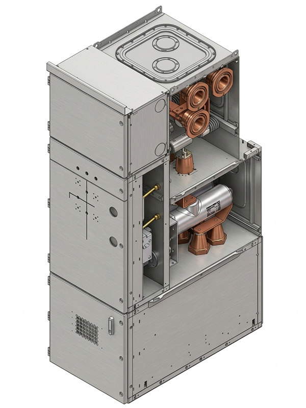
The dielectric performance of the switchgear is the core guarantee of safe operation. Assembly involves the installation of insulators (such as epoxy insulator), conductor connections, and rigorous internal cleaning. Even with a flawless design, the presence of contaminants during assembly can severely degrade performance.
(A) Insulator Installation Control
Before installation, insulators must be thoroughly cleaned to remove dust and grease. During the process, physical impacts or scratches must be avoided. Precise positioning and uniform clearances are required to prevent electric field distortions that lead to Partial Discharge (PD).
(B) Conductor Connection Control
- Surface Preparation: Oxide layers and impurities must be removed from connection surfaces to ensure a high-conductivity interface.
- Torque Control: For bolted connections, tightening torque must be strictly regulated to ensure a secure fit and prevent loosening over time.
- Insulation Shielding: Connection points must be properly shielded or insulated to prevent exposure or insufficient creepage distances.
(C) Internal Cleanliness Control
Cleanliness is paramount. The assembly environment must be strictly controlled for dust. Upon completion, the interior must be thoroughly cleaned using compressed air blowing or vacuuming to ensure it is free of any debris before final sealing and gas filling.
IV. MV GIS Sealing and Protection Control
The core objective of sealing is to prevent gas leakage while barring moisture, dust, and corrosive substances from entering the enclosure. The equipment must meet IP67 protection standards (for gas compartments) with an annual leakage rate below 0.05%.
(A) Seal Selection and Inspection
Seals must be selected for their resistance to corrosion, high temperatures, and aging. Ethylene Propylene Diene Monomer (EPDM) is the industry standard. Incoming seals must be inspected for physical damage, deformation, or aging. Elasticity and hardness must also be verified against assembly specifications.
(B) Installation Control
- Sealing Surface Preparation: Surfaces must be meticulously cleaned and verified for flatness and smoothness. Any burrs or scratches must be polished out to ensure a flush interface.
- Installation Norms: Seals must be seated correctly without twisting or misalignment. A dedicated sealant should be applied uniformly to O-rings to enhance performance, with careful control over quantity to avoid contaminating internal components.
- Torque Management: Tightening torque must be balanced; insufficient torque leads to leaks, while excessive torque causes permanent deformation (compression set), stripping the seal of its resilience.
(C) Sealing Performance Testing
GIS switchgear manufacturers typically utilize the helium leak detection method to inspect welds, sealing surfaces, and valves. Before shipping, gas pressure is monitored via a SF6 manometer or SF6 gas density relay to ensure constancy. Any identified leaks must be addressed through re-welding or seal replacement, followed by re-testing until the unit is fully compliant.
V. Overview of Core Quality Control Points in C-GIS Manufacturing
| Core Stage | Key Control Objective | Key Technical Parameters / Tools |
| Enclosure Fabrication | Gas-tightness and structural precision | Laser cutting (±0.1mm accuracy), Laser welding |
| Gas Processing | Dielectric strength and moisture control | Automated vacuum cycling, Helium leak detection (< 0.05%) |
| Insulation Assembly | Prevention of Partial Discharge (PD) | Cleanliness management, Torque verification (secure connection) |
| Sealing Protection | Long-term operational reliability | EPDM seals, IP67 protection (gas compartments) |
Conclusion and Outlook
The manufacturing of Medium-Voltage Gas-Insulated Switchgear (C-GIS) is a rigorous industrial process. Through the precise management of the four core pillars—enclosure welding, gas cycling, insulation assembly, and sealing protection—we can ensure that the equipment maintains exceptional electrical performance throughout its 30-year service life. Practice has proven that a meticulous quality control system is not merely a guarantee of compliance, but the foundation of reliability under extreme operating conditions.
Looking ahead, the evolution of C-GIS manufacturing is increasingly focused on environmental sustainability. With rising global attention on the greenhouse effect, the research and application of eco-friendly alternative gases (such as dry air or nitrogen) to replace SF6 has become a critical direction. This transition not only sets higher benchmarks for gas-tightness but also requires manufacturing breakthroughs in electric field optimization and material compatibility. By refining every process detail and embracing low-carbon technologies, the C-GIS industry will continue to safeguard the stability and safety of power systems worldwide.
Get A Free Quote


Power your projects with long-lasting switchgear and switchgear components from Liyond.
