

 EN
EN RU
RU


July 21, 2026
In transmission and distribution network architecture, to achieve comprehensive monitoring and control of power grid operating conditions, reliable and accurate signal interaction between the high-voltage and low-voltage sides is essential. The potential transformer (referred to as PT, often called Voltage Transformer or VT in international standards) serves as the core electrical interface designed specifically for this purpose. The operational status of this device is directly linked to the accuracy of power system monitoring data, the promptness of protective logic, and the overall safety of the grid. Consequently, it commands consistent attention in electrical engineering design and equipment selection.
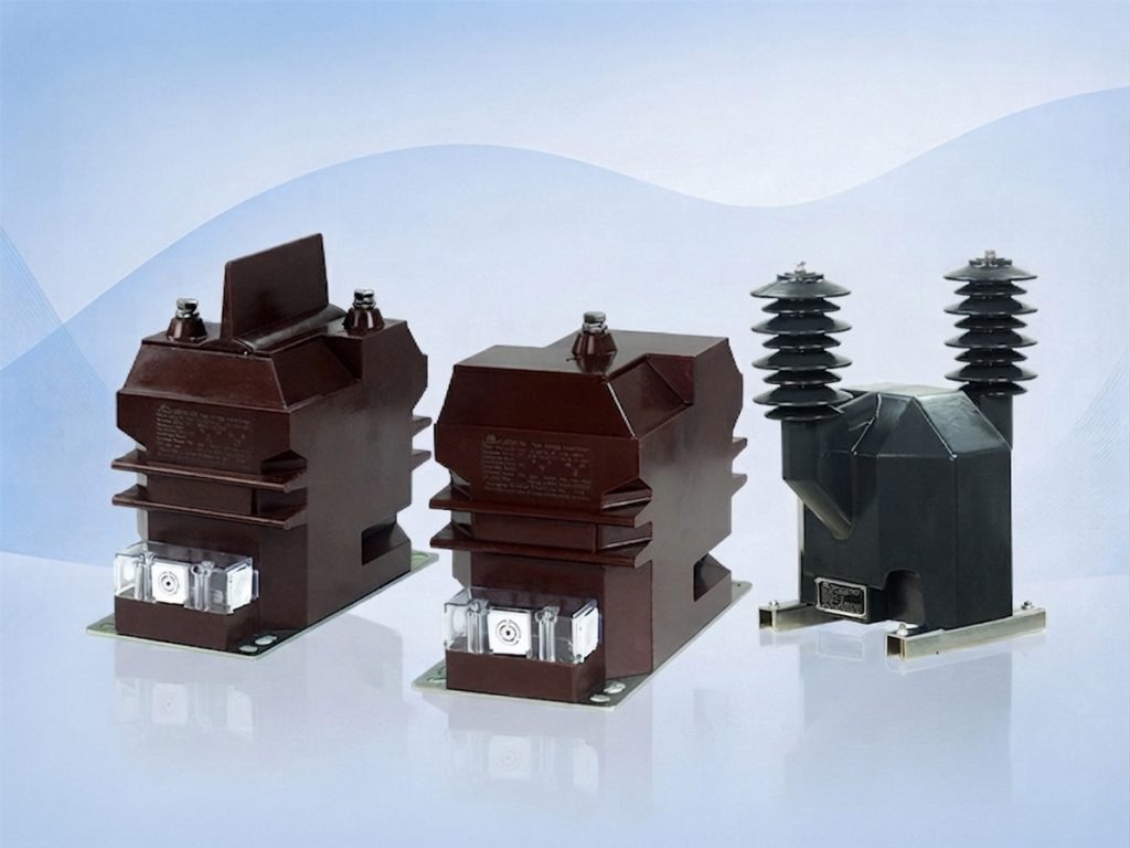
What is a potential transformer?
From a technical definition perspective, a potential transformer is a type of instrument transformer used specifically for voltage transformation. Its design goal is to achieve voltage level conversion while maintaining a constant proportional relationship and phase consistency between the secondary output voltage and the primary input voltage. Its core functional mechanisms encompass the following three aspects:
- Electrical Isolation: The PT provides physical isolation between the high-voltage primary circuit and the low-voltage secondary circuit. This isolation ensures that measuring instruments, relay protection devices, and operators connected to the secondary side are shielded from the direct hazards of the high-voltage grid, safeguarding both equipment and personnel safety.
- Signal Standardization: Potential transformers convert various voltage levels within transmission and distribution networks (such as 10kV, 35kV, and 110kV) into standardized secondary voltage signals (such as 100V or 100V/√3). This uniform output standard eliminates the need for secondary devices to be custom-designed for different primary voltage levels, thereby enhancing system compatibility.
- Precision Parameter Transmission: The transformer not only accurately reflects the magnitude of the primary voltage but also maintains a strict phase relationship. For the synchronized operation, energy billing, and fault analysis of power systems, such precise parameter transmission serves as a foundational prerequisite for logical control.
Potential transformer construction
From the perspective of physical structure, a potential transformer is a stationary electrical device based on the principle of electromagnetic induction. When exploring the types of potential transformer, their external encapsulation form is custom-designed according to the application environment; for instance, indoor switchgear predominantly utilizes epoxy resin vacuum casting, whereas outdoor applications typically select oil-immersed or gas-insulated structures. Despite significant variations in external encapsulation, their internal core components consist of the following fundamental parts:
- Magnetic Core: The magnetic core serves as the magnetic flux pathway for the potential transformer, typically formed by stacking high-permeability silicon steel sheets. Its primary function is to effectively minimize hysteresis and eddy current losses while ensuring that magnetic flux can be efficiently transmitted between windings. The design quality of the magnetic core directly dictates the excitation characteristics and measurement accuracy of the transformer.
- Primary Winding: The primary winding is the conductor section connected to the high-voltage side power system. This winding features a higher number of turns and a relatively fine wire gauge, designed to withstand the full voltage level of the grid and generate the required excitation current. The connection method between the primary winding and the high-voltage circuit depends on the system grounding type and voltage level.
- Secondary Winding: The secondary winding is the circuit that outputs standardized low-voltage signals. It possesses fewer turns and a coarser wire gauge, acquiring voltage from the primary winding via electromagnetic coupling. Typically, multiple secondary windings can be configured within a transformer to separately meet the independent power supply requirements of measuring instruments, relay protection devices, or monitoring systems, thereby achieving electrical isolation between measurement and protection circuits.
- Insulation and Encapsulation System: The insulation system is core to ensuring the long-term stable operation of the transformer under power-frequency high voltage. Its structural design exhibits clear process variations according to application scenarios:
Outdoor Applications: Typically adopt oil-immersed, SF6 gas-insulated, or advanced solid-insulation (such as epoxy resin casting) structures. While ultra-high-voltage environments rely on oil/gas designs for extensive insulation and heat dissipation, medium-voltage outdoor applications increasingly favor compact, maintenance-free epoxy resin structures to suit modern pole-mounted or kiosk substations.


Indoor Applications: The core focus is adapting to the compact installation space within switchgear, with epoxy resin vacuum casting serving as the mainstream solution. This process delivers exceptional electrical insulation performance while ensuring high mechanical strength and good moisture resistance, satisfying complex interlock installation requirements inside medium-voltage switchgear.


Potential transformer working principle
The working principle of a potential transformer follows the law of electromagnetic induction. Its basic operational logic lies in realizing proportional conversion between the primary side (high-voltage side) and secondary side (low-voltage side) voltage, while maintaining electrical isolation between the two circuits.
The specific operating mechanism primarily encompasses the following three core stages:
- Magnetic Coupling: When the primary winding is connected to the measured high-voltage line, the AC voltage generates an excitation current, which subsequently establishes an alternating magnetic flux in the core. According to electromagnetic induction, this magnetic flux traverses both the primary and secondary windings simultaneously, thereby inducing electromotive force across the terminals of the secondary winding.
- Transformation Ratio: The magnitude of the secondary output voltage depends on the turns ratio of the transformer. Through precise design of the turns ratio between the primary and secondary windings, the transformer linearly scales down the high voltage levels in the grid to a standardized secondary-side voltage (such as 100V or 100V/√3). This process ensures that secondary-side devices receive feedback signals maintaining a strict proportional relationship with the grid voltage.
- Phase Displacement: Aside from magnitude transformation, a PT must maintain a strict phase relationship between the secondary output voltage and the primary input voltage during operation. Such phase consistency is vital for power system synchronous operation, power direction discrimination, and complex relay protection logic. For a high-quality potential transformer, phase error must be strictly restricted within specified limits to ensure that power monitoring systems can accurately judge the real-time operating status of the grid.
Why potential transformer secondary should not be short-circuited?
Unlike current transformers, potential transformers are inherently constant voltage source devices. The load impedance on their secondary side is typically designed to be extremely high to ensure that secondary current remains at a negligible level under normal operating conditions. Once a short circuit occurs on the secondary side of a potential transformer, it triggers severe electrical faults:
- Surging Short-Circuit Current: According to electromagnetic induction principles, when the secondary-side load impedance approaches zero, constrained by the extremely low internal impedance of the transformer, the secondary-side current instantly surges to tens of times its rated value or even higher.
- Core Saturation and Overheating: The massive secondary current generates an intensely strong demagnetizing magnetic flux, disrupting the originally balanced electromagnetic state inside the transformer and causing the core to rapidly enter the saturation region. Due to the thermal effect of winding resistance, high currents cause winding temperatures to rise sharply, and the instantaneously released Joule heat easily burns out the winding insulation layer.
- Equipment Damage Risk: Sustained short-circuit conditions will not only directly burn out the transformer itself but may also cause the thermal decomposition of insulation materials, generating toxic gases or provoking further electrical short circuits, thereby rendering the transformer completely unserviceable and potentially affecting adjacent control or protection devices.
Therefore, under no circumstances should the secondary side of a potential transformer be short-circuited, and corresponding short-circuit protection devices (such as fuses or automatic air circuit breakers) must be configured during design and operation and maintenance to cut off potential overcurrent loops. For further routine operation specifications and safety maintenance recommendations, you can refer to our Potential Transformer Operation Guide.
Potential transformer functions and applications
Through physical step-down and electrical isolation, potential transformers translate high-voltage grid conditions into standardized voltage signals that secondary devices can process within power systems. Owing to their characteristics, potential transformers enjoy widespread application across power grids; common applications include the following:
Substations and Power Dispatching
Potential transformers act as data entry points for substation monitoring systems (SCADA), providing dispatchers with real-time busbar voltage monitoring. Concurrently, they transmit voltage signals to relay protection devices; when short circuits or ground faults occur in the grid, protection devices rely on these signals to identify faults and trip power supplies rapidly, preventing accident escalation.
High and Low-Voltage Switchgear
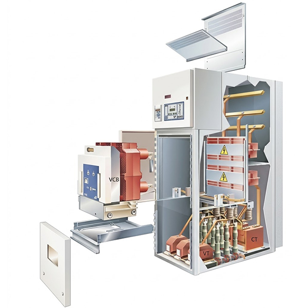
Within switchgear, potential transformers are installed near busbars to directly monitor supply voltage. Beyond providing real-time data display for field instruments, their output voltage signals are integrated into the electrical interlocking loops inside the cabinet to judge whether equipment is energized, effectively preventing safety hazards such as misoperation of handcarts under load.
Distributed Energy Integration
At the grid-connection interfaces of photovoltaic, energy storage, and wind power systems, potential transformers are utilized to detect the point of common coupling (PCC) voltage. Grid-connection controllers monitor the phase and frequency of this point in real time to ensure the grid closes breakers under synchronized conditions, avoiding transient currents caused by phase deviations and safeguarding power quality.
Industrial Power Distribution and Energy Efficiency Management
In large-scale industrial power distribution systems, potential transformers are employed to monitor high-voltage incoming lines and the operational status of critical loads. They not only provide metering inputs for electricity meters but also serve as reference elements for reactive power compensation devices, helping enterprises monitor power factor in real time to achieve energy conservation, consumption reduction, and operational optimization of distribution systems.
Conclusion
In summary, potential transformers are not only foundational physical devices for achieving high- and low-voltage electrical signal conversion, but also core sensing components supporting power system automation, protection logic, and energy efficiency management. Whether in relay protection loops safeguarding traditional grid safety or in monitoring and stable control systems supporting secure and steady renewable energy grid integration, their high-precision voltage transformation performance serves as an essential foundation for systems to acquire accurate data and secure safe operation.
Liyond is committed to providing global customers with high-performance electrical switchgear and core components. We can supply you with high-precision, high-reliability instrument transformers products and assist you in completing model selection and technical interfacing for switchgear matching projects. Should you require product specifications or further technical consultation, please feel free to contact our professional team at any time.
Related Blogs:
What’s the Difference between Current and Voltage Transformer
Types of Potential Transformers
Get A Free Quote


Power your projects with long-lasting switchgear and switchgear components from Liyond.
