
 EN
EN RU
RU

March 03, 2026
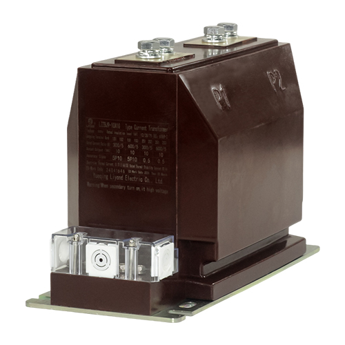
In the design and selection of medium-voltage (MV) switchgear, the installation layout of Current Transformers (CTs)—the core components for metering and relay protection—serves as a critical factor in balancing electrical insulation, thermal dissipation, and mechanical strength. An optimized layout of the current transformer not only significantly reduces copper consumption and overall costs but also directly impacts maintenance accessibility, temperature rise control under high-current conditions, and internal arc pressure relief performance during fault events.
Current engineering practices primarily utilize epoxy resin cast-type (block-type) and window-type current transformers. Due to their through-conductor structural characteristics, window-type CTs are subject to stringent clearance and creepage distance requirements under insulation coordination standards, resulting in relatively fixed positioning. In contrast, cast-resin CTs offer greater flexibility, leading to four mainstream installation configurations based on spatial requirements and technical specifications: layout behind spouts, vertical rear-mounting, horizontal base-mounting, and integrated modular configurations. Designers must achieve an optimal configuration between layout flexibility and insulation coordination based on specific operating conditions.

1. CT Installed behind Contact Boxes
Installing the CT horizontally behind the switchgear spout insulators (contact boxes) minimizes the primary conductor path between the contact and the transformer, offering a distinct advantage in copper cost control. While this positioning demands higher precision for transformer mounting and support, its compact footprint reserves ample space for bottom cable connections. This configuration is particularly suitable for distribution units with lower short-circuit current ratings and standard current levels.
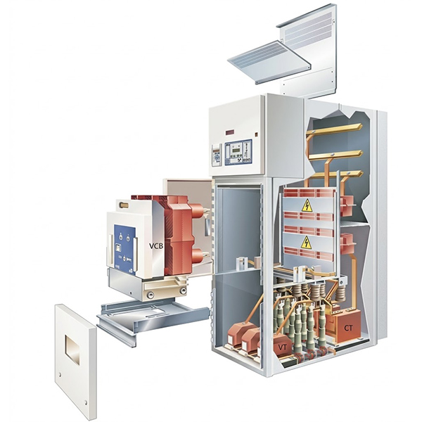
2. CT Installed in the Rear of Switchgear
Vertical installation of the CT in the rear of the switchgear is a mainstream design for high-current applications, primarily due to its optimized natural convection path within the cable compartment. By positioning the CT vertically, this layout eliminates the airflow obstruction common in traditional mounting plates, which often leads to heat accumulation at the tulip contact interface. During temperature rise tests, this arrangement provides a vital thermal margin for critical connection points. Furthermore, a large-area rear pressure relief channel ensures that in the event of a 40kA internal arc fault, the relief flaps respond within 6–7 milliseconds, minimizing the impact of destructive pressure on the enclosure and structural switchgear components.
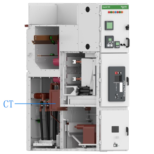
3. CT Installed on the Cabinet Base
Horizontal installation of the CT on the cabinet base is primarily adapted for “front-serviceable” switchgear designs. This configuration allows technicians to perform routine winding tests and secondary wiring inspections directly from the front of the unit without removing the rear panels. Especially in back-to-wall installations or space-constrained substations, base-mounting not only meets insulation coordination requirements but also ensures the accessibility and visibility of earthing switches and associated interlocking mechanisms.
4. CT Installed in Integrated Modules
Integrating the CT into a dedicated module below the spouts represents the evolution of modular switchgear design, achieving deep integration between the CT and the earthing switch. This architecture eliminates redundant connecting busbars, significantly increasing the power density of compact switchgear. While integrated designs impose specific constraints on vacuum circuit breaker dimensions and internal compartment height, their “complete assembly, complete replacement” characteristic greatly simplifies manufacturing processes and enhances product consistency across production lots.
Technical Comparison of CT Configurations
| Installation Layout | Pros | Cons | Typical Applications |
| Behind Contact Boxes | Reduced copper usage; simple structural design. | Poor thermal dissipation at high currents; restricted pressure relief. | Low-current units; low short-circuit rating requirements. |
| Rear-mounted (Vertical) | Excellent temperature rise control; unobstructed pressure relief. | Increased footprint in the rear of the cabinet. | High-current applications; standardized switchgear designs. |
| Base-mounted (Horizontal) | Ease of maintenance (ideal for back-to-wall installations). | Potential space constraints for cable termination. | Front-serviceable (front-access only) requirements. |
| Integrated Module | Modular assembly; supports miniaturization. | Higher precision required for circuit breaker dimensions. | Compact switchgear; high-density layouts. |
Conclusion
In summary, the layout of CTs within a MV switchgear is not static; it requires a comprehensive trade-off between rated current, short-circuit ratings, maintenance requirements, and enclosure dimensions. From cost-driven spout-mounting and performance-oriented vertical rear layouts to maintenance-friendly base-mounting and highly integrated modular schemes, each configuration reflects a specific design philosophy. In the future of power system construction, characterized by standardized design schemes and equipment miniaturization, selecting an optimized layout that balances thermal safety with operational convenience will be key to enhancing the overall operational quality of MV switchgear.
Get A Free Quote


Power your projects with long-lasting switchgear and switchgear components from Liyond.