
 EN
EN RU
RU
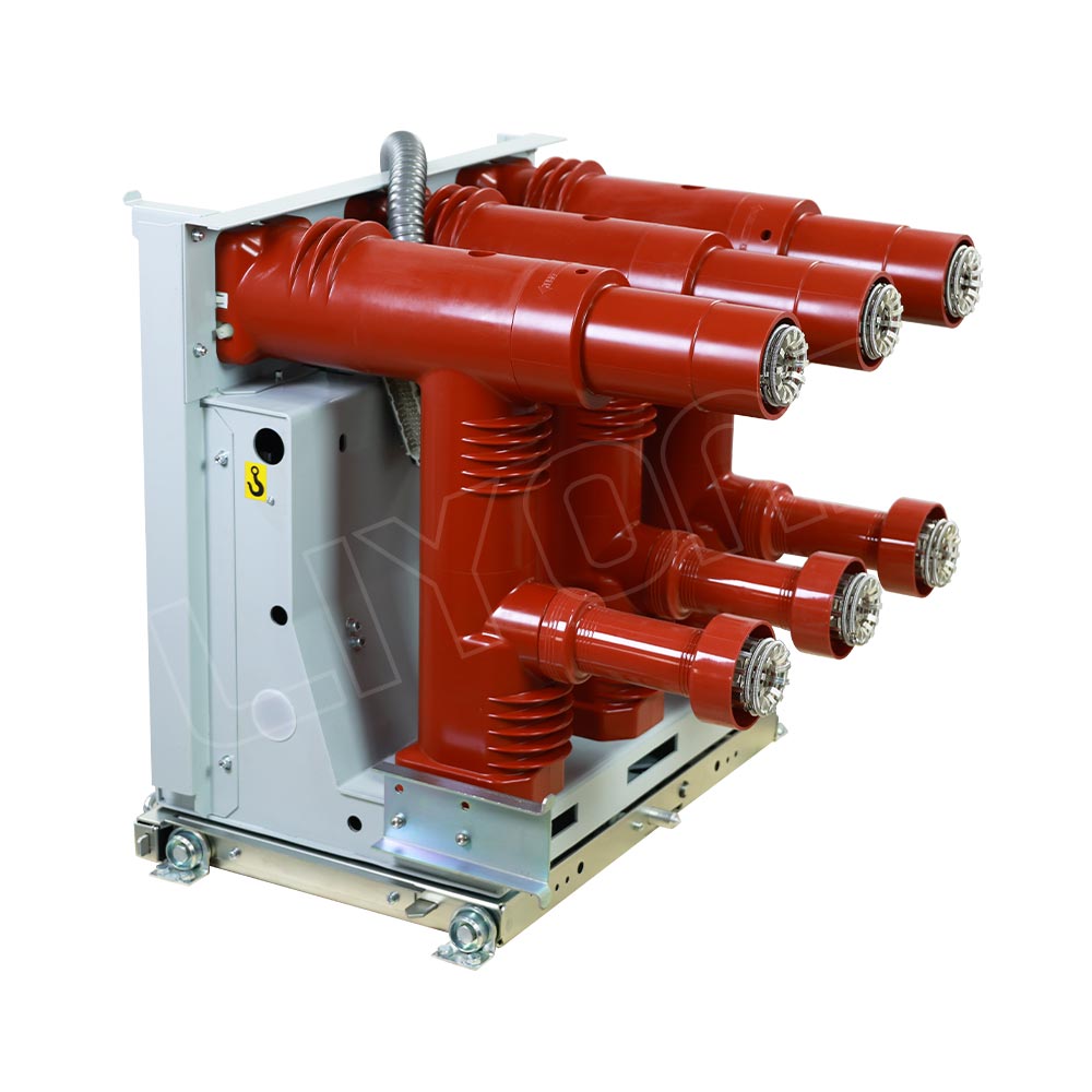
VZF(R)-12 Handcart Type Vacuum Load Break Switch-Fuse Combination Unit
The VZF(R)-12 series is a new-generation vacuum load break switch–fuse combination unit, designed based on advanced engineering concepts and evolving market demand. It is widely applied in metal-clad air-insulated switchgear and complies with GB3804-2004 and GB16926-1997 standards. Operating safely and reliably under rated technical conditions, it is ideal for medium-voltage distribution networks.


 Electrical Products
Key Features of VZF(R)-12 vacuum load break switch–fuse combination unit
Innovative Structure
The vacuum interrupter and actuator are arranged front-to-back, simplifying the transmission path, reducing energy consumption, and enhancing mechanical reliability.
Solid-Insulated Pole Design
The epoxy-molded “T-type” poles are manufactured using APG (Automatic Pressure Gelation) technology, integrating the vacuum interrupter and terminals. This ensures high insulation performance, minimizes contamination and external adjustments, and enhances environmental resistance.
Enhanced Insulation & Compatibility
Top-mounted horizontal fuse arrangement ensures optimal electric field distribution inside metal-clad switchgear, improving dielectric strength and simplifying site testing — even without high-voltage fuse simulators.
Custom Vacuum Interrupter
Compact and long-life interrupter with optimized magnetic field design and wear-resistant contacts provides:
Low contact resistance
High mechanical endurance
Strong arc extinction capability
Modular Operating Mechanism
Includes modules for closing, tripping, enclosure, main shaft, and secondary circuits. This modular design:
Speeds up delivery
Simplifies maintenance
Supports standardized production
Technical Advantages of VZF(R)-12 vacuum switch
Withdrawable design compatible with mid-mounted switchgear, solving the incompatibility issues of traditional fixed-type load break switches.
Advanced interlock system prevents misoperations and ensures operator safety.
Built-in energy storage mechanism for rapid actuation.
Visible mechanical and electrical fuse tripping indication.
Breaks short-circuit currents up to 25kA, providing dual protection through fuse and relay coordination.
Ideal for replacing traditional fuse trucks and protecting station transformers or grounding transformers.
Technical Parameters of VZF(R)-12 vacuum switch
Mechanical Characteristic Parameters
| No. | Item | Unit | Parameter |
| 1 | Contact gap | mm | 9±1 |
| 2 | Contact pressure spring travel | mm | 4±1 |
| 3 | Phase center distance | mm | 210/275 |
| 4 | Opening/closing time difference | ms | ≤2 |
| 5 | Contact closing spring time | ms | ≤3 |
| 6 | Average closing speed | m/s | 0.4~0.8 |
| 7 | Average opening speed | m/s | 1.0~1.4 |
| 8 | Closing time (rated voltage) | ms | ≤60 |
| 9 | Opening time (rated voltage) | ms | ≤30 |
| 10 | Main circuit resistance | mΩ | ≤250 |
| 11 | Allowable wear thickness of contacts | mm | 3 |
Technical Parameters
| No. | Name | Unit | VZF-12/T630-20 Vacuum Load Switch | VZFR-12/T125-50 Vacuum Load Switch – Fuse Combination |
| 1 | Rated voltage | kV | 12 | 12 |
| 2 | Power frequency withstand voltage (phase/earth) | kV | 42 | 42 |
| 3 | Lightning impulse withstand voltage (phase/earth) | kV | 75 | 75 |
| 4 | Rated current | A | 630 | 125 (Fuse) |
| 5 | Rated short-circuit breaking current | kA | – | 50 (Fuse) |
| 6 | Rated short-time withstand current | kA | 20 | – |
| 7 | Rated peak withstand current | kA | 50 | – |
| 8 | Rated short-circuit making current | kA | 50 | – |
| 9 | Rated cable charging breaking current | A | 16 | – |
| 10 | Rated transfer current | A | – | 3150 |
| 11 | No-load transformer breaking capacity | kVA | 1250 | |
| 12 | Electrical life | times | 10000 | |
| 13 | Partial discharge level | pC | ≤5 | |
Dimensions(Suitable for 800mm width metal-enclosed switchgear)

Transformer Capacity and Fuse Selection
Since fuses can interrupt large short-circuit currents in less than 10 ms — with a breaking capacity up to 50 kA — they provide highly effective protection for transformers.
When coordinating transformers with fuses (see Table 1), it is essential to consider the inrush current that the fuse may be exposed to. Therefore, the rated current of the fuse should be at least 1.6 times the transformer’s rated current. Designers must also take into account potential fluctuations in power system parameters and provide a reasonable safety margin when selecting fuses.
When using fuses to protect high-voltage motors, the starting frequency of the motor must also be considered. In cases of frequent starting, the fuse may not have adequate time to cool down between operations, potentially affecting its performance.
Table 1: Fuse Selection for Transformer Protection
| Transformer primary voltage (kV) | Transformer Capacity (kVA) | Fuse Model | Fuse rated current A |
| 6.6 | 200 | XRNT-10 | 31.5 |
| 250 | 40 | ||
| 300/315 | 50 | ||
| 400 | 63 | ||
| 500 | 80 | ||
| 630 | 90 | ||
| 10 | 30 | XRNT1-12 | 3.15 |
| 50 | 6.3 | ||
| 80 | 10 | ||
| 100 | 16 | ||
| 125 | |||
| 160 | 20 | ||
| 250 | 25 | ||
| 300/315 | 31.5 | ||
| 400 | 40 | ||
| 500 | 50 | ||
| 630 | 63 | ||
| 750/800 | 71 | ||
| 80 | |||
| 1000 | |||
| 90 | |||
| 1250 | 100 | ||
| 112 | |||
| 150/160 | 125 |
Get in Touch with Liyond
We're here to help! Connect with our team for expert support and personalized solutions.
Related 12kV Indoor Load Break Switch
Check out these related products you might also be interested in.
Get A Quote


Power your projects with long-lasting switchgear and switchgear components from Liyond.